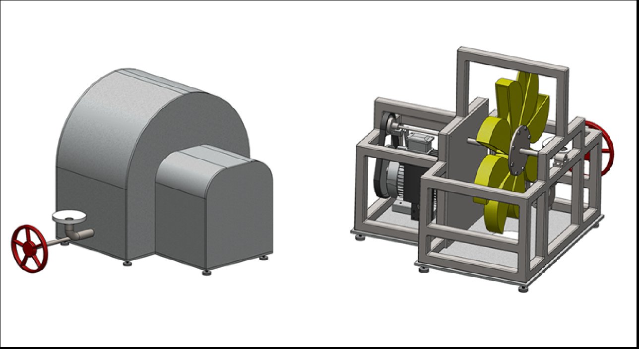
Off-grid communities need power. Rivers are everywhere.
Many rural and developing communities lack access to reliable electricity but sit near flowing water year-round. Large hydroelectric infrastructure is prohibitively expensive and complex to deploy at small scale. The design challenge was to build a small, portable, low-cost turbine system that could generate meaningful electrical output from a pressurized water supply using common tools and materials.
Pelton-wheel impulse turbine
An impulse turbine was chosen over a reaction turbine because it suits low-to-moderate head pressures and is mechanically simpler — no submerged components, no sealed housing required around the runner. The Pelton wheel design uses high-velocity water jets directed at bucket-shaped blades, converting the kinetic energy of the jet into shaft rotation with high efficiency at the design operating point.
The system consists of three main assemblies: the nozzle and spear-valve assembly (flow control), the bucket wheel and shaft (energy conversion), and the motor and belt-drive (power output). My contribution focused on the third assembly.
Motor housing & belt-driven drivetrain
I designed and modeled the motor housing geometry, mounting system, and full belt-driven drivetrain that transmits torque from the turbine shaft to the generator motor. Key design decisions included:
Shaft exit geometry: The turbine shaft passes through the housing wall via a flanged port, requiring a sealing interface that keeps water out while allowing free rotation. The housing wall thickness and port geometry were sized for structural rigidity without unnecessary weight.
Pulley ratio: A fixed pulley-and-belt arrangement steps up the shaft RPM to match the motor's operating speed range. The belt drive was chosen over a gear train for simplicity, cost, and ease of field replacement.
Motor mounting: The motor bracket was designed with slotted mounting holes to allow belt tension adjustment without disassembly — a practical consideration for a system meant to be assembled in the field.
Spear valve & nozzle assembly
Water enters the system through a nozzle with an internal spear valve — a tapered needle that slides axially to vary the nozzle exit area, and therefore the jet velocity. The spear is actuated by an external hand wheel, giving the operator real-time control over turbine speed and output power without valves upstream of the unit.
This is the same fundamental control mechanism used in full-scale Pelton installations — scaled down to a hand-operated version appropriate for a portable unit.
Full SolidWorks model, assembly constraints validated
The project was completed as a fully constrained SolidWorks assembly with all mating conditions satisfied. Physical fabrication was outside the scope of ME 1670, but the model was designed explicitly with DFM in mind — every part was modeled to reflect real stock sizes and real manufacturing constraints.
Assembly design is a constraint problem
The most challenging part of this project wasn't modeling individual parts — it was making the assembly work as a system. Belt tension, shaft alignment, bearing fit, and housing geometry are all coupled; changing one affects the others. Working through those interdependencies in SolidWorks before committing to a design taught me to think about assembly constraints as a first-class design input, not an afterthought.